
Most Amateurs know that a typical 2 meter repeater, for example, uses a duplexer. A duplexer protects a repeater station from itself by providing R.F. isolation between the transmitter and receiver. It may also provide some protection from external sources depending on the design. It will allow the transmitter and receiver to use the same antenna assuming the antenna is suitable for duplex operation. Beware of antennas for the Amateur market.
So exactly what are we providing protection from? There are two main things, transmitter noise (sideband noise) and receiver desensitization (and smoke from coming out of the receiver front end)J.
All transmitters produce some noise on either side of the carrier. The further away from the carrier, the lower the noise becomes. If the transmitter noise that falls on the repeater receiver frequency is not attenuated sufficiently it will effectively degrade the receiver performance. A valid signal will have to overcome this noise to be heard. The next question might be is how much protection or isolation is required? Now we need to look at how much noise the transmitter produces at the receiver frequency. Every transmitter manufacturer should know this and will likely have tables or curves with this information. Unfortunately many are reluctant to provide this information. The only reason I can think of for not providing this information is marketing. If the competitorís transmitter is a few dB better they donít want this information known. In reality this means virtually nothing because we can take this in consideration in our isolation calculations. You can measure the noise yourself if you have a suitable spectrum analyzer and a notch filter set-up, something that is normally unavailable to most Amateurs. The notch filter is used to effectively increase the dynamic range of the spectrum analyzer. An isolation TEE is also required otherwise you will smoke the input of the spectrum analyzer. Some equipment manuals and sales brochures do provide sideband noise specs at a couple of frequencies away from carrier. It may be possible to extrapolate some useful data using the provided information.
Letís assume we have the required information and the noise is 90 dB down from carrier on the receiver frequency. Also, letís assume we have a 30 Watt repeater. We cannot work with Watts so we need to convert it to dBW or dBm. We normally work with dBW here. The formula is dBW = 10log(Power). Thirty Watts of power is 14.8 dBW. Ninety dB down from 14.8 dBW is ñ75.2 dBW. This is the power level at our receiver frequency. A typical repeater receiver may have a sensitivity of ñ146 dBW, that is, 0.35 microvolts for 12 dB SINAD. We will need to supply from the duplexer 70.8 dB isolation just to meet the receiver spec. Adding another 10 or 15 dB for the duplexer isolation will give us a safety margin. This isolation is provided in the transmitter leg of the duplexer.
The next thing we look at is receiver desens. Receiver desensitisation is caused by a strong off frequency signal effecting the receiver front end performance. In our case it would be the repeater station's transmitter. It is unlike transmitter noise that manifests itself as a signal falling on the receiver frequency. The station manufacturer will likely have this information in the form of a curve or table. Like the transmitter noise spec many are unwilling to provide this information. If you are lucky and talk to the right people, the information is sometimes available. At one time I had a conversation with the engineering manager of a manufacturer that produced data radios. The information he provided to me was simple but useful. The information was that the receiver would desens with an in-band signal of greater that ñ30dBm. That particular case was the 406 to 430 MHz commercial band. Using this as an example lets see how much isolation would be required from the duplexer.
Let's use the transmitter power indicated above, 30 Watts or 14.8 dBW. We will need to get the transmitter signal at the receiver port below ñ30 dBm or ñ60 dBW. The difference between 14.8 dBW and ñ60 dBW is 78.4 dB. This is the isolation required. You will want to add a safety margin to this. This isolation is provided in the receiver leg of the duplexer.
The point at which a receiver will desens can be measured using two signal generators, a suitable combiner and a SINAD meter or AC voltmeter. The combiner is a 3 port device that takes the signals from the signal generators and has the output feeding the receiver. It provides isolation between the generators. One generator will be on the receiver frequency and the other on the repeater transmitter frequency. A basic reference level is determined (12 dB SINAD for example) using the generator on the receiver frequency. The level of the other generator is increase until a predetermined desens level is reached. A major equipment manufacture uses 6 dB degradation of 12 dB SINAD for this level. Care must be taken to insure that any sideband noise from the generator on the repeater transmitter frequency is not effecting these readings.
The simplest form of a duplexer is the reject type. It can be typically constructed with notch cavities or a helical resonator design.
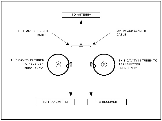
Above is a drawing of a basic reject duplexer using notch cavities. In reality, using only 2 notch cavities will likely not provide sufficient isolation. Note that the cavity in the transmitter leg is tuned to the receiver frequency and the cavity in the receiver leg is tuned to the transmitter frequency. Also note that the cables going from the cavities to the TEE are a specific length.
This type of duplexer will provide virtually no protection from strong signals other than from the transmitter it is connected to. This is an important consideration if the repeater is installed on a site with other stations and especially with rooftop antenna installations where no vertical antenna separation is provided. Many Amateur installations use a variation of this design that may provide a limited amount of isolation for receiver desens only caused by another station's transmitter. It cannot provide protection from another station's transmitter sideband noise and may only provide a limited amount of transmitter noise protection for another station's receiver.
DISCLAIMER: