|
|
On occasion the 456.5 KHz lower sideband crystal would quit working on my AX-190 H.F. receiver. Apparently bad crystals are a common problem with this receiver. It did not happen very often just when I really wanted to listen to something. The upper sideband crystal worked OK. When the LSB crystal was working the output was a little lower than the USB crystal as observed on an oscilloscope. Since I did not have a spare crystal and was not sure where I could get one I decided to change the oscillator transistor. This seemed to work good for a while but later the crystal started to quit again.
I had a couple of 455 KHz crystal and decided to try one just to see if I could pull the frequency or possibly the crystal was a bit off frequency. The crystal was right on 455 KHz and I could not pull it. What I did notice was that the output of the 455 crystal was about twice as high or more than either the USB or LSB crystal. As mentioned above I was not sure where I could get a crystal and since the output of the 455 KHz crystal I tried was so much higher than either the USB or LSB crystal I thought I might also need a USB crystal later as well.
I decided to take a different approach and build a BFO. Since the BFO is adjustable it could cover the USB crystal frequency as well solving another pontential problem.
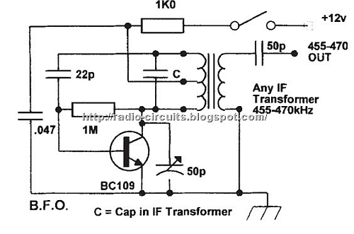
An internet search turned up a number of 455 KHz BFO circuits. I used this one since I had all the parts except for the transistor indicated.
|
|
|
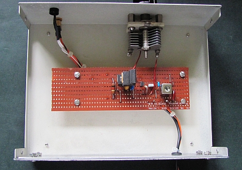
For the transistor I used a 2N3904 since it was the first one I came across in my selection of transistor that should work. I built the circuit on a piece of copper clad Vero board. Bench tests indicated that the circuit was very sensitive to voltage variations causing the frequency to shift. Powering the BFO from a regulated source was required. Also noted was that the lower the voltage the better the output waveform looked. The receiver used a simple 9.6 voltage regulator and I was initially going to power a 5 volt 7805 regulator to be located on the BFO board from this 9.6 volt supply. I later decided to get the power from the unregulated 14.5 volt supply from the receiver. The BFO board evolved quite a bit from the original layout. The BFO as it is now is powered from the +5 volts taken from the 7805. I left space on the board in case I wanted to add more circuitry like buffering but since it works well without any, this will likely not happen.
I used an enclosure that was much bigger than required but that's what I had and it brought the cost of the project down to zero. The enclosure was initially used for a data switch, 1 DB25 connector for the input and 4 for the output.
|
|
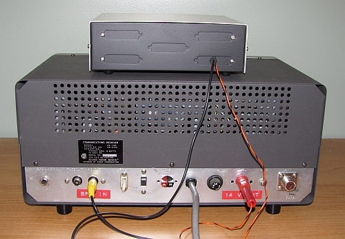
On the back of the receiver there are 2 connectors that likely would never be used. They are VFO OUT and HFO OUT. I am now using the VFO OUT connector for the BFO IN. The HFO OUT connector was removed and replaced with a banana jack. I have lots of these and it fit perfectly in the hole. It is now used to take power from the receiver to power the BFO. The return is through the coax shield used for the BFO IN.
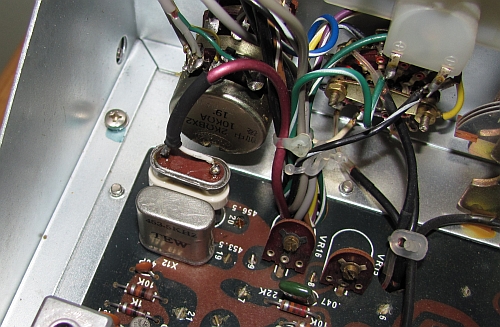
Internal to the receiver the unregulated power supply voltage is fed to the banana jack through a 150 Ω resistor. The 1 KΩ resistor shown on the BFO schematic is not used. A crystal socket was added where the LSB crystal was originally installed by soldering wire leads to the crystal socket and adding heat srink tubing to the wires to add some mechanical stability. An old HC6/u crystal holder was taken apart and the bottom part was used by soldering the shield and inner conductor of the coax from the BFO to the pins (see photo below).
The BFO was calibrated by setting the variable capacitor to the mid range and adjusting the transformer slug to 455 KHz using a frequency counter. This is a very coarse adjustment. The current draw by the BFO is about 18 ma. That includes the led pilot light I added. I assume this slight increase in current is OK for the power supply.
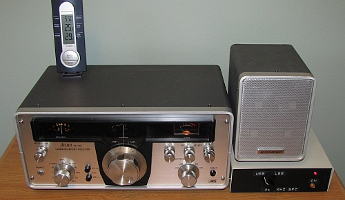
For operation the Function switch on the receiver is set to LSB for both USB and LSB (and CW). Operation of the BFO is quite smooth and the frequency stability is OK. I prefer using the BFO over the fixed crystal frequencies as it provides more flexibility in tuning by allowing the BFO frequency to be placed anywhere in the receiver's IF bandpass.
Update December 4, 2014
I found the long term stability of the BFO isn't as good as I had hoped. I suspect it is caused by the transformer used. I added an 18 pf piston trimmer in parallel with the variable capacitor. This allowed some fine tuning of the frequency without re-adjusting the transformer. I added the trimmer to the BFO front panel to make the access easier.