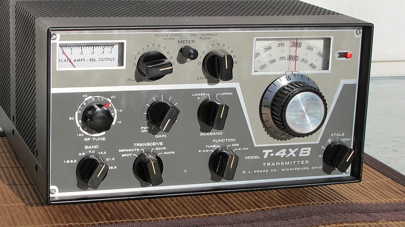
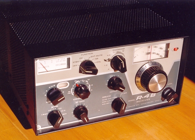
A number of years ago I bought this Drake T-4XB to match my R-4B H.F. receiver that I bought new in the early 1970's. I originally wanted the receiver to use with VHF/UHF converters.
The T-4XB is a mainly tube design SSB/CW/AM H.F. transmitter. This T-4XB transmitter was advertised on a local Shop & Shop by a seller who lived out of province. The seller claimed there were no issues with it and worked fine but when it arrived it did not work.
The transmitter came with an original instruction manual but unfortunately the schematic was missing. A decent copy of the schematic was difficult to fine and in fact I still don't have one. The one(s) on the BAMA website were pretty much useless. I did find one on the Internet that was about 90% readable and I used it for troubleshooting. Update: January 7, 2014. Thanks to Steve, K7LZJ, I now have a good copy of the schematic.
Initially several problems were identified. The transmitter used a soldered-in 8 amp fuse in the filament circuit. It had been replaced before and the replacement fuse was the wrong value. Also, the soldering job was unacceptable. After replacing the fuse with the correct value I looked into the other problems. A visual inspection found a broken capacitor in the 160 meter circuit. A visual inspection of the power amplifier compartment and final circuitry prompted me to take a closer look at the components. It looked like it got very hot in there. I identified and replaced several resistors that were way out of tolerance. The next thing I noticed was that the band select crystal oscillator was not working. I traced the problem to a bent open rotor contact on it's wafer switch. After repairing the wafer switch the transmitter still did not work and I decided to put it aside for a while.
I recently decided (2 years later) that I should finally get it working. The next problem I found was an open resistor in the driver circuit. The transmitter now started to show a little output on some bands but was far from working properly.
The manual had alignment instructions. It specified it was for “touch-up” alignment only and I soon discovered that the transmitter required more that a touch-up. I followed their alignment sequence but developed my own alignment method. An oscilloscope really came in handy here. The test equipment I ended up using included an oscilloscope, a DC meter with RF probe, a frequency counter, DVM and a Bird Termaline Wattmeter/Load. I also used a homebrew RF sampler that was used at the transmitter output. The sample port was connected to an oscilloscope and proved very useful for setting the carrier oscillator, carrier balance and optimizing the output power. The transmitter was way out of alignment and I suspect someone might have tried the “touch-up” alignment instructions without identifying and repairing the main problems first. After completing the transmitter alignment it put out good power up to 20 meters. The output power on 15 and 10 meters seems a little low and it could probably use new output tubes but overall the transmitter works. The 2 final tubes are 6JB6's and are expensive. One other issue is the dial calibration on 15 meters. The problem is the band crystal that is off frequency by 7.5 KHz. It a little inconvenient to use on 15 meters but not a show stopper. The receiver VFO could also be used eliminating the problem.
The meter and dial lamps that were originally in the T-4XB were previously replaced with higher voltage lamps. These “new” lamps didn't provide quite enough illumination. The original lamps were 6 volt #47's. I had some of these lamps and replaced the other lamps with them. I like running these incandescent lamps at lower voltages to extend their lives. I selected an appropriate value resistor (and Wattage) to reduce the voltage on the lamps by about 30 percent. This still provided enough illumination. I also did the same to the matching R-4B receiver.
So far the transmitter reliability and on air reports have been very good.