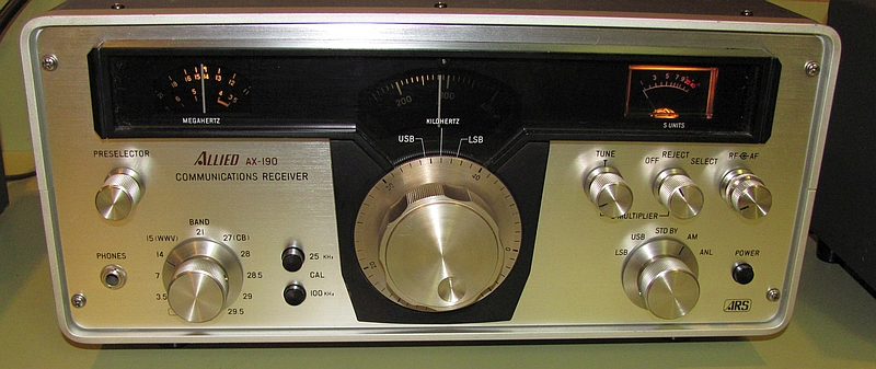
I bought this receiver with matching speaker from a local Ham with the understanding it was intermittent and appeared to be a little deaf on some bands.

Quite a bit of information for this receiver is available on the Internet including a service manual. It is early all solid state design and was produced in the early 1970's. It covers the Ham bands from 80 through 10 meters plus CB with the exception of the WARC bands. One additional band crystal may be added for another 500 KHz segment between 3.5 and 30 MHz. You might be able add others if you were willing to sacrifice other existing 500 KHz band segments like CB. The receiver uses a manually adjustable front end preselector that is divided into 2 ranges, 3.5 MHz to 10 MHz and 10 MHz to 30 MHz. On the back of the receiver there are two outputs that could be used to interface with an appropriate transmitter. One is an HFO output which is a band crystal output and the other is a VFO output. It looks like they were considering making a matching transmitter that could be operated in the transceive mode. I don't believe this ever happened.
One of the intermittence was caused by a shorting variable capacitor in the Q multiplier circuit. Adjusting the plates solved this problem. The rest were the results of dirty potentiometers and switch contacts.
The radio is fairly easy to work on and has lots of test points on the circuit boards. On the bands above 10 MHz the receiver seemed somewhat less lively than the ones below. After doing some initial troubleshooting I decided to do an alignment. The service manual included an alignment procedure but there appeared to be some mistakes and omissions in it and also it could have been more through in it's instructions. The manual indicated that the second IF (455 KHz) could be aligned without the use of a sweep generator. This was good for me as the generator I have with sweep capabilities did not cover 455 KHz. I would suggest that anyone wanting to do a second IF alignment on an AX-190 use a sweep generator as it is very difficult to get IF symmetry without one.
After the alignment the receiver still seemed quiet on the upper bands above 10 MHz although the sensitivity looked OK. I am interested in hearing from anyone with this type of receiver if they have or have not noticed this. The preselector circuitry is pretty much the only thing that could cause this to happen. When switching to the bands above 10 MHz additional passive components are added to the preselector circuitry. The alignment of the preselector when smoothly with no anomalies in the tuning. I did not do a formal sensitivity test but I did applied a 1 microvolt signal with 100 percent modulation (1 KHz tone) into the receiver on 10 meters and the S/N seemed good. I also did some on air testing with a 10 meter MOSFET preamp I used years ago for satellite work and it didn't do much other than driving the S-meter a little higher.
As mentioned above the receiver has a built-in Q multiplier. It works but in the reject mode the notch appears to be to broad and also not very deep. I did not do any detailed testing on this.
Overall it doesn't seem to be a bad receiver for it's vintage and initial cost. It's stable, has 1 KHz dial resolution and so far I haven't noticed any anomalies like overload issues or image problems.
I plan to use it as part of my AM station set-up.
UPDATE APRIL 10, 2011
When I initially got this receiver I spent some time on the Internet collecting information on it. From what I found it was normal to have some AC hum from the speaker. This receiver also had hum so I considered it normal. The hum showed up when the receiver was in the standby position or when the receiver was muted during a transmission. I am currently using this receiver with a Heathkit DX-60B transmitter. The hum wasn't all that bad but was a bit annoying. I decided to do something about it. The power supply uses a full wave rectifier circuit feeding a 2200 microfarad filter capacitor. There was an output from this feeding the audio output transistors directly. I replaced the filter capacitor with a 4700 microfarad and the hum was reduced to a point where it became barely noticeable. Today's electrolytic capacitors are much smaller and there was plenty of space on the power supply board to install it. I checked the original 2200 microfarad capacitor on a capacitance bridge and it tested OK. I don't expect to see any adverse effects with this change and so far there has been none.
UPDATE December 4, 2014
I bought another AX-190 receiver at a Ham flea market a few months ago. It had the same problem as this one with a lazy LSB crystal. See A BFO for the Allied AX-190 Receiver for more information. I did a couple of thing to try to resolve the problem. I added the lazy lower sideband crystal (456.5 KHz) from the first radio in parallel with the lower sideband crystal in the latest radio just to see what would happen. This actually worked, I assume it increases the "Q". I also noticed that when I placed the oscilloscope probe on the crystal lead the circuit was a little slower to start. I think the probe capacitance is about 20 or 30 pF. This lead me to remove the 20 pF, c68, at the base of the oscillator transistor. Removing the cap., had very little effect on the actual frequency. I don't know if just removing this cap., would improve the situation. The receiver has been in operation for a few months now and so far it has worked fine.